Our Location
304 North Cardinal St.
Dorchester Center, MA 02124
304 North Cardinal St.
Dorchester Center, MA 02124
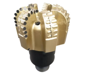
The extraction of underground resources, whether for oil, gas, water wells, or geothermal energy, relies heavily on the mechanical and hydraulic efficiency of the drilling system. At the very center of this operation is the drill bit, a complex engineering mechanism designed to crush, shear, or cut through various geological formations. While the physical teeth or cutters of the drill bit perform the mechanical destruction of the rock, the hydraulic energy of the drilling fluid, often referred to as drilling mud, is equally vital to the success of the operation. This fluid must be circulated down through the drill string, ejected out of the drill bit face, and forced back up the annular space between the drill pipe and the borehole wall. The primary mechanism controlling this fluid ejection is the nozzle system integrated directly into the drill bit body.
The nozzles are essentially precise, replaceable orifices made of highly wear-resistant materials like tungsten carbide. Their primary function is to convert the high-pressure, low-velocity fluid column inside the drill string into a series of ultra-high-velocity fluid jets. These jets strike the bottom of the borehole and the face of the cutting elements to clear away freshly generated rock chips before they can be crushed a second time by the rotating bit. The size of these nozzles dictates the overall hydraulic performance of the bottom-hole assembly, directly affecting parameters such as Total Flow Area, pressure drop, jet velocity, mud discharge rate, and bottom-hole crossflow patterns.
Understanding the relationship between nozzle geometry and mud discharge is essential for preventing common downhole drilling performance issues. For instance, if the nozzles are poorly sized, the drilling mud may fail to lift the heavy cuttings away from the cutting structures, leading to a phenomenon known as bit balling, where sticky clay or shale adheres to the bit face and destroys its cutting ability. Conversely, improper sizing can lead to excessive backpressure on the surface mud pumps, causing mechanical failures or eroding the borehole walls due to uncontained turbulent energy. Therefore, optimizing the nozzle sizes is a balancing act that requires a deep dive into the fluid dynamics of mud discharge and the physical laws governing fluid mechanics downhole.
To analyze how individual nozzle changes alter mud discharge performance, one must look at the overarching mathematical framework of Total Flow Area. The Total Flow Area represents the cumulative cross-sectional area of all the active fluid exits located on the face of the drill bit. In most standard tricone roller bits, there are three primary nozzles, while modern Polycrystalline Diamond Compact bits can feature anywhere from four to over a dozen distinct jet ports. The Total Flow Area is usually calculated in square inches or square millimeters and serves as the primary metric when planning pump output and predicting system pressure variations.
When a drilling engineer adjusts the diameter of even a single nozzle, the Total Flow Area shifts exponentially because area is proportional to the square of the nozzle radius. A small decrease in nozzle diameter causes a significant reduction in the path of least resistance for the drilling mud. Under a fixed mechanical pump displacement rate from the surface, reducing the Total Flow Area forces the fluid to accelerate drastically as it enters the constricted nozzle throat. This behavior is governed directly by the continuity equation of fluid dynamics, which states that for an incompressible fluid, the volumetric flow rate must remain constant across varying cross-sections. Therefore, as the area shrinks, the velocity must increase to allow the same volume of mud to discharge in a given unit of time.
However, the surface pumps cannot maintain a perfectly constant flow volume if the restriction becomes too severe. Every fluid system has an upper operating pressure ceiling determined by the mechanical design of the liners, valves, and manifold systems. When the Total Flow Area is constrained too far by utilizing small-diameter nozzles, the fluid resistance generates an immense pressure drop across the bit face. This backpressure propagates all the way up the drill string, requiring higher pump pressures to maintain the desired flow rate. If the pressure required exceeds the safety or mechanical limits of the surface equipment, the flow rate must be manually or automatically decreased, directly altering the total volume of mud discharged at the bottom of the hole.
When a drill bit is outfitted with smaller nozzle configurations, the immediate physical outcome is a dramatic escalation in fluid exit velocity. As the drilling fluid is squeezed through the tight boundaries of a small orifice, the pressure energy built up within the drill string is rapidly converted into kinetic energy. The fluid exits the nozzle as a highly focused, concentrated jet stream that can reach velocities exceeding one hundred meters per second. This high-speed stream carries a massive amount of kinetic energy and creates a powerful localized impact force when it collides with the bedrock at the bottom of the hole.
This intense localized impact force is highly beneficial for dislodging tough, compacted rock cuttings from the tooth profiles of the bit and the rock face itself. The high-velocity mud discharge sweeps across the bottom of the hole, penetrating the tiny fractures created by the mechanical cutting structures. This action helps to instantly lift the fragments into the upward-moving annular stream before they can form a cushion layer that dampens the effectiveness of subsequent bit rotations. Furthermore, the high-velocity fluid discharge creates a localized zone of low pressure around the edges of the jet due to the Bernoulli principle, which draws surrounding fluid and smaller suspended particles into the main stream, enhancing the cleaning efficiency of the crossflow.
Despite these clear advantages, small nozzles present distinct operational risks that can severely impact the continuity of mud discharge. The most immediate threat is nozzle plugging, or bridging, which occurs when solid particles suspended within the drilling fluid become mechanically wedged inside the restricted nozzle opening. Drilling mud is rarely a pure liquid; it is a complex suspension containing weighting materials like barite, chemical additives, and recycled rock fragments that may have bypassed the surface shale shakers. If the nozzle diameter is too narrow, large rock fragments or clumps of unhydrated polymer can completely block the orifice. This blockage halts mud discharge from that specific port, causing an instantaneous pressure spike on the surface gauges and disrupting the hydraulic balance of the bit, which can quickly lead to localized overheating and premature cutter destruction.
Implementing larger nozzle sizes inside the water drill bit shifts the hydraulic profile toward high volumetric displacement at lower overall velocities. When the individual nozzle openings are broadened, the Total Flow Area expands significantly, offering much less mechanical resistance to the oncoming fluid column. For a given surface pump pressure, the drilling mud can pass through the bit face with ease, minimizing the pressure drop across the bit nozzles. This allows the surface mud pumps to operate within a highly stable, lower-pressure envelope, which reduces mechanical wear on pump pistons, liners, and dampeners while extending the overall operational life of the surface fluid delivery loop.
The primary benefit of a larger nozzle layout is the ability to maximize the total volume of fluid discharge per minute, measured in gallons per minute or liters per minute. In soft, loose, or unconsolidated formations such as topsoil, soft clays, and loose sands, the mechanical strength of the formation is incredibly low. In these environments, the sheer volume of mud discharge is critical because large amounts of soil and rock are excavated very quickly. The drill bit creates massive volumes of loose debris that must be flushed away immediately to prevent the borehole from filling up with its own cuttings. The wide, high-volume fluid curtains produced by larger nozzles provide excellent volumetric sweeping action, ensuring that huge volumes of loose material are moved up into the annulus efficiently.
However, the trade-off of expanding the nozzle diameter is a critical drop in fluid jet velocity. Because the fluid exit path is wide, the mud discharges from the bit as a slower, broader stream with significantly less concentrated kinetic energy. If the velocity drops below a critical threshold, the jet streams lose their ability to effectively clean the individual cutters or penetrate the sticky mud layers that tend to accumulate on the bit body. In sticky shale formations, this lack of high-velocity impact allows the clay particles to pack tightly between the cutting teeth. Without a high-velocity stream to blast the clay away, the bit becomes balled up, the rate of penetration drops to near zero, and the drill string may become stuck due to the accumulation of poorly managed debris around the bottom-hole assembly.
The cleaning efficiency of a borehole is directly linked to the mechanical rate of penetration, and both parameters are heavily influenced by how nozzle selection governs mud discharge patterns. When rock is fractured by a drill bit, it creates a temporary vacuum under the freshly cut chip due to hydrostatic pressure differences. If the mud discharge does not immediately sweep into this zone to balance the pressure and lift the chip, the ambient hydrostatic pressure of the mud column will force the chip back down against the rock face. This phenomenon is known as the chip hold-down effect, and it acts as a major drag on drilling speed, forcing the bit to repeatedly regrind old material rather than cutting fresh rock.
Optimizing nozzle sizes ensures that the mud discharge has the perfect balance of velocity and volume to overcome this chip hold-down effect. The ideal configuration creates a powerful crossflow across the bottom of the borehole. This crossflow behaves like a high-speed fluid broom, sweeping from one side of the hole to the other, lifting cuttings out of the path of the advancing cutters and transferring them to the upward-moving annular column. When the bottom of the hole is clean, every tooth impact or diamond cutter engagement strikes virgin rock, which maximizes the mechanical work done per revolution and results in a substantially higher rate of penetration.
If the nozzles are incorrectly matched to the formation and the pump capacity, mud discharge patterns deteriorate into stagnant fluid zones or chaotic eddies at the bottom of the hole. For example, if all nozzles are perfectly uniform and identical in size, the fluid streams can collide with each other in the center of the bit, canceling out their horizontal kinetic energy and creating a dead zone where cuttings accumulate. This accumulation causes localized abrasive wear on the drill bit body, eroding the steel matrix that holds the cutters in place. By carefully selecting non-uniform or asymmetrical nozzle combinations, engineers can deliberately direct the mud discharge to create a continuous, unidirectional spiral flow path that carries all rock debris smoothly away from the bit face and straight up into the annulus.
To understand how these nozzle principles are applied in real-world environments, it is helpful to look at the commercial drill bit models and specialized hydraulic systems produced by major global equipment manufacturers. These companies invest heavily in computational fluid dynamics and specialized manufacturing techniques to create proprietary nozzle patterns and bit bodies that maximize mud discharge efficiency across various geological environments.
Baker Hughes
Vanguard Series: This premium roller cone product family is engineered to maximize mechanical and hydraulic durability in tough environments. The Vanguard bits are designed with optimized watercourse geometry that supports the implementation of extended nozzle tubes. These extended nozzles minimize the distance between the fluid exit point and the borehole bottom, allowing the high-velocity mud discharge to strike the rock face with minimal energy loss through the ambient mud column.
Talon High-Efficiency PDC Bits: Designed for high-speed directional drilling, the Talon series features an asymmetric nozzle layout. Instead of pointing straight down, the nozzles are precisely angled toward the specific cutting blades that experience the highest rock volumes. This targeted mud discharge ensures that the high-load cutters remain cool and free of debris, maintaining a high rate of penetration in sticky or transitional formations.
Halliburton
FX Series (FXD / FXS): The FX product family represents Halliburton’s elite line of Polycrystalline Diamond Compact bits, utilizing advanced cutter technology combined with their specialized DatCI (Design at the Customer Interface) modeling process. The nozzle configurations in the FX series are highly customizable, allowing for the integration of specialized vector nozzles that direct fluid discharge at precise angles to create a continuous vortex flow across the bit face, maximizing cutting evacuation.
MegaForce Tricone Bits: This heavy-duty roller cone line is built for harsh structural environments. The MegaForce features reinforced nozzle shrouds made from erosion-resistant steel alloys. These shrouds prevent the high-velocity mud discharge from eroding the bit body itself when using small, high-pressure nozzle configurations, ensuring the mechanical integrity of the cone bearings remains intact over long drilling runs.
National Oilwell Varco (NOV)
ReedHycalog Titan Series: The Titan series focuses on large-diameter roller cone applications where managing mud discharge volume is a massive operational challenge. These bits feature extra-large fluid watercourses capable of accepting high-flow nozzle inserts. This allows operations to run maximum volumetric pump rates to flush out thousands of pounds of rock cuttings per hour without risking high backpressures or internal structural erosion.
Tektonic PDC Bits: The Tektonic platform is designed with an emphasis on fluid evacuation paths. The bit face features deeply sculpted junk slots—the large channels between the cutter blades where mud and rock fragments travel. The nozzles are placed at the base of these junk slots, ensuring that the discharging fluid immediately sweeps the cuttings out of the mechanical cutting zone and into the main annular exit stream.
Terelion
Avenger Mining Series: Terelion focuses heavily on high-performance tools for industrial mining and water well applications. The Avenger tricone line is built to handle highly variable drilling fluids, including air, mist, and heavily weighted muds. The nozzle retention systems are designed for fast field replacement, allowing operators to rapidly change nozzle diameters on the rig floor to adjust mud discharge characteristics based on shifting geological formations.
D-Force Abrasive Series: Engineered explicitly for highly abrasive formations like quartzite and granite, the D-Force series integrates specialized tungsten carbide nozzle inserts with extended profiles. These profiles help guide the fluid discharge stream directly onto the formation face to rapidly cool the cutting structures while ensuring that hard, abrasive cuttings are pushed away immediately before they can scour the bit body.
Ensuring optimal mud discharge requires rigorous field maintenance practices and proactive inspection protocols for both the drill bit and its nozzle components. Because drill bit nozzles are subject to continuous exposure to high-pressure, abrasive fluids filled with solids, they are vulnerable to extreme mechanical wear. Over extended operating periods, the inner bore of a tungsten carbide nozzle can suffer from internal erosion, especially if the drilling fluid contains high concentrations of sharp quartz sand or poorly conditioned solids. This internal erosion gradually expands the inner diameter of the nozzle, leading to an unintended increase in Total Flow Area, an associated drop in mud jet velocity, and a general degradation of the bottom-hole cleaning performance.
To manage and mitigate these operational risks, drilling crews must execute a comprehensive inspection sequence whenever a drill bit is brought to the surface or prepared for run-in.
O-Ring Inspection and Seal Verification: Every twist-in or thread-in nozzle relies on a high-density elastomeric O-ring to create a complete fluid seal between the outer surface of the nozzle and the internal receptacle of the drill bit body. During inspection, this O-ring must be closely checked for signs of thermal degradation, tearing, or flattening. If the seal fails downhole, high-pressure drilling mud will bypass the nozzle orifice and leak through the structural threads. This fluid bypass creates a localized erosion pathway, known as a washout, which can quickly cut through the steel bit body, completely destroying the bit and causing a total loss of mud discharge control.
Nozzle Thread Lubrication and Torque Optimization: The mechanical threads inside the nozzle pocket and on the nozzle body must be thoroughly cleaned with a wire brush to remove dried mud, scale, and metallic debris. Prior to installation, a specialized anti-seize compound with a high metallic content must be applied evenly to the threads. This compound prevents galling—a form of structural welding caused by high friction—and protects the assembly from corrosion. The nozzle must then be tightened using a calibrated torque wrench according to the manufacturer’s specifications; under-torqueing can cause the nozzle to vibrate loose downhole, while over-torqueing can crack the brittle tungsten carbide body.
Orifice Calibration and Internal Geometry Profiling: The internal bore of each nozzle must be measured using precise go/no-go gauges or digital calipers to confirm that no internal erosion has occurred. Even a minor diameter increase of a fraction of an inch across multiple nozzles can collectively disrupt the drilling hydraulics plan, dropping the fluid velocity below the threshold required to clean the bit face. Furthermore, the internal entry cone of the nozzle must be checked for chipping or pitting; any surface irregularity can cause fluid turbulence, accelerating localized erosion and distorting the mud discharge jet pattern.
By establishing these meticulous maintenance routines, operators can ensure that the selected nozzle configurations perform exactly as designed, providing stable, predictable mud discharge dynamics throughout the entire life of the bit run.
